For heat meters and cold meters

For heat meters and cold meters

Temperature probes for direct installation

Steadily rising energy costs and strict legal requirements require highly accurate billing of the thermal energy consumed in heating or cooling systems.
An important component of the heat and cooling meters used for this purpose are the precise temperature probes for determining the temperature difference at the flow and return of the heating.

Temperature probes for measuring thermal energy, which are permissible for the demanding use in billing systems, are also available from us ready paired on request.

The Testo Sensor GmbH not only produces temperature probes for heat and cold meters according to your customer-specific specifications, but also keeps an eye on all standards and guidelines for proper approval.

Details for temperature probes for universal use (DS  /  PS)

Technical requirement for heat meter probes (universal use)

To ensure that heating and cooling costs can be accurately allocated to the consumer and producer, a very accurate temperature measurement must take place. This follows strict legal requirements, because only in this way is a qualitative framework for reliable and comparable temperature measurements and thus heat and cold quantity counts possible.

Therefore, the conformity according to MID (Measuring Instruments Directive) of the EU, the European regulations for heat metering, is essential for our probes. There is currently no overarching European regulation in force for cold quantity metering; national regulations apply, e.g. according to the Measuring and Calibration Ordinance.

You can rest assured that the temperature probes from Testo Sensor GmbH fully meet or exceed all requirements for operation in conjunction with heat and cold quantity meters.

Qualification temperature probe heat and cold meter

General information

Measuring range (depending on sensor and connection cable) ±0 °C bis +105 °C (PUR / PVC cable)
±0 °C bis +130 °C (TPE cable)
±0 °C bis +150 °C (Silicone cable)
Limit value temperature difference 3 K to150 K
Response time < 4s (depending on the design e.g. Ø 5.0 / 5.2 mm significantly faster)
Measurement stability 10 years ( Please note recalibration cycles according to MID / MessEV)
Measuring elements Please config (Pt100, Pt500 or Pt1000)
Tolerance Class B according to EN60751
Connection type Two-Wire technology
Measuring principle resistiv (resistance value)

Maximum measurement current
(calculated from the maximum
permissible power loss of
of 0.5 mW)

Pt100: 1178 μA at 2,5 m and 0,0095 Ohm/m
Pt500: 795 μA at 12,5 m and 0,0095 Ohm/m
Pt1000: 562 μA at 255 m and 0,0095 Ohm/m
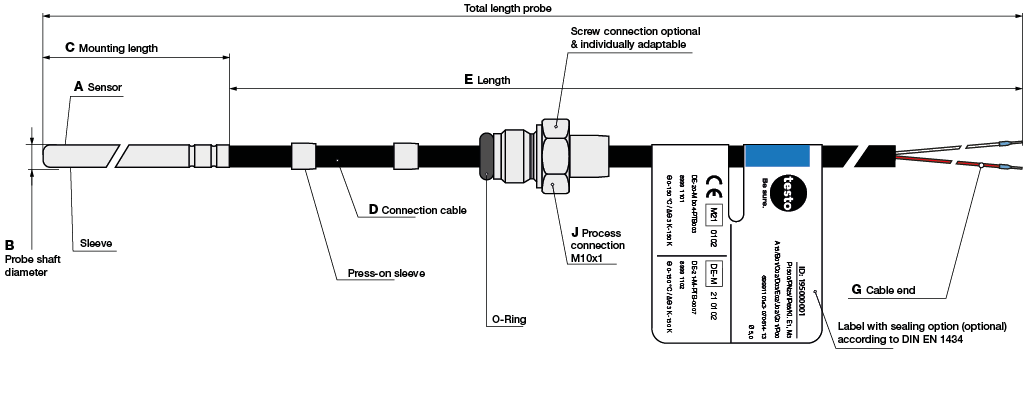
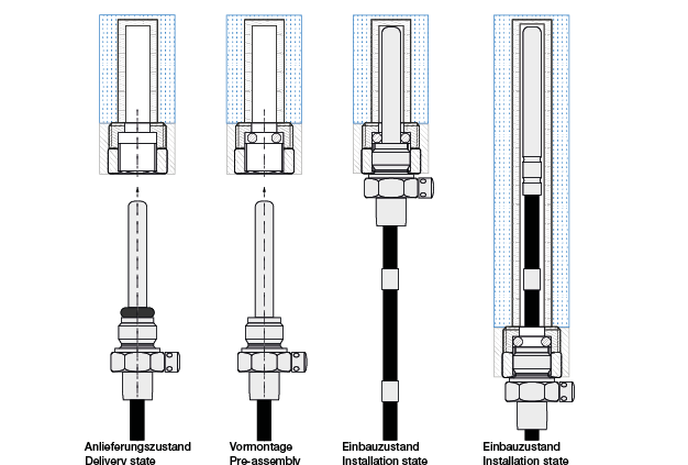
Installation Direct installation acc.to DIN EN 1434 or installation in immersion sleeves acc.to tolerance list
Minimum immersion depth ≥ 20 mm
Max. pressure P S 25 at flow velocity water 2 m/s
cable length according to DIN EN 1434 Pt100 max 2,5 m | Pt500 max 12,5 m | Pt1000 max 25 m
Environmental conditions Protection class: IP 65 (acc.to DIN 40050) | Electrical: E1| Mechanical: M3 | Climatic: -25 °C to +70 °C

Configurable options

Please configure your temperature probe for heat and cold meters
A – Measuring element B – Ø Probe shaft C – Mounting length
Code Meas.element Accuracy Code Ø probe shaft Code Mount. length
A13 Pt100 Kl. B1) B01 5,0 mm C01 26,0 mm
A15 Pt500 Kl. B1) B02 5,2 mm C02 27,5 mm
A23 Pt1000 Kl. B1) B03 6,0 mm C03 38,0 mm
1)dT = ±(0,30 °C + 0,005 · T) acc. to IEC 751 / EN 60751 | Conn. type: 2-wire C04 60,0 mm
Other probe shaft Ø between 5.0 and 6.0 mm as well as other mounting lengths and customised screw connections are available on request.
J – Process connection D – Material connection cable
Code Standard Code Conn. Color From To Out Color Q mm2
J00 without screw connection D01 2-wire black ±0°C +105°C PVC rt, ws 0,22
D02 2-wire black ±0°C +150°C Silicone rt, ws 0,22
J02 M10 x 1 incl.
locking screw &
sealing device
D03 2-wire black ±0°C +130°C TPE rt, ws 0,22
D04 2-wire black ±0°C +105°C PUR rt, ws 0,22
Further or customised screw fittings are available on request
E – Length G – End seleeves P – Standard
Code Length Code Standard Code Standard
E01 1,5 m G01 Wire end ferrules (standard) P00 not paired
E02 2,5 m G02 Tin-plated connection leads
(only for probes permanently
connected to the calculator)
P01 paired according to DIN EN 1434
        P02 paired according to DIN EN 1434 with conformity assessment / marking
according to MID (heat)
        P04 paired according to DIN EN 1434 with conformity assessment / marking
according to MessEG (cold Austria)
We offer other cable lengths between 0.3 m and 25 m in increments of 0.5 m. Please note the maximum lengths (depending on the sensor): Pt100
max 2.5 m | Pt500 max 12.5 m | Pt1000 max 25 m

Technical drawing & mounting instructions

Technical Drawing

Poss. configuration

A = Meas. elements
B = Ø Probe shaft
C = Mount. length
D = Cable material
E = Cable length
J = Process connection
G = Wire end
P = Standard
Installation instructions
The installation of temperature probes in pipelines (qp ≤ 6) must be carried out directly in new installations in Germany. Please carry out direct installation of temperature probes in accordance with DIN EN 1434-2 and the technical guideline TR-K8 (see following figure).

  • The temperature probes shall only be installed in the immersion sleeves approved for the probes on the list of tolerated immersion sleeves.
  • In immersion sleeve installation, identical immersion sleeves (type, mounting length and inner diameter) must be used for each probe of a pair. 

  • The use of heat conductive paste is not permitted.
  • In Germany, when installing temperature probes for short immersion sleeves, the immersion sleeves must be marked with their respective approval number.
  • The temperature probes must be installed up to the bottom of the immersion sleeve.
  • Process connection: Tighten the locking screws.
  • The temperature probes must be sealed and subjected to a final function test.
  • The temperature probes can be designed for installation in long immersion sleeves. This version has cable clamping sleeves on the cable (see illustration below).
  • Before mounting, check that the correct cable clamping sleeve is used by measuring the length of the immersion sleeve.
  • The temperature probe is fixed in the immersion sleeve with a lateral locking screw on the cable clamping sleeve.

Our certifications & standards

Data sheets for temperature probes for heat meters (universal use)

Your contact person for temperature probe on heat meters

Scroll to Top